PWM and CAN
These are the two main ways we use for transmitting information across motor controllers, IMUs, sensors, and more.
For the electrical test, make sure you know which controllers use PWM and which use CAN (as well as any other specifics, if necessary)
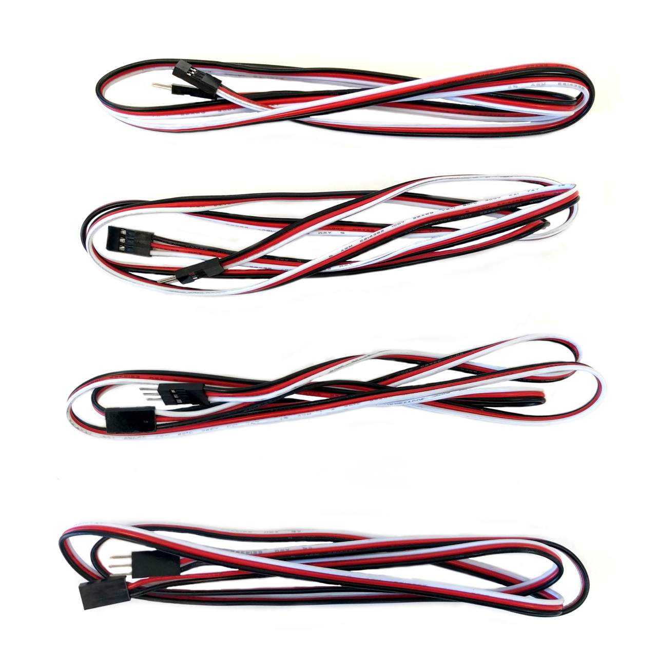
- PWM: Stands for Pulse Width Modulation. Uses three individual wires colored white, red, and black respectively. Provides an input signal that is manipulated to control the speed of the spinning motor. For the motor controllers that use PWM, it is able to affect the speed by rapidly switching from full voltage to zero voltage at a specific frequency to reach that specific speed. Each device wired through PWM needs to be connected to a corresponding port on the PWM section of the RoboRIO.
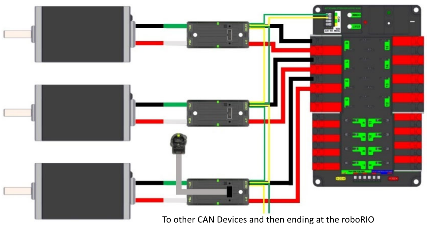
- CAN: Stands for Controller Area Network. Yellow and green wire (which is matched to corresponding ports on each device).
- Unlike PWM, CAN wiring goes in a "chain". This chain usually starts at the RoboRIO, and ends at the PDP, connecting to each motor controller and other CAN device sequentially (each one of these devices will have a CAN ID so that it can be referenced in the code). However, it is important to note that this chain can have different starting or ending points. In that case, you need a 120 ohm resistor at each end of the chain (this is built into the RoboRIO and PDP CAN Bus terminals already so that's why we wouldn't need these resistors if we use those two devices at the end of the chain).
- The PDP CAN slot contains a jumper that you can adjust to turn this built-in resistor on and off. This should be on if the PDP is one of the terminals of the chain, but should be off if it isn't.
- The RoboRIO does not have this jumper, so it has to be at one of the ends of the chain.
- The PDP CAN slot contains a jumper that you can adjust to turn this built-in resistor on and off. This should be on if the PDP is one of the terminals of the chain, but should be off if it isn't.
- Remember, when making this chain, the yellow wire connects to yellow wire and green connects to green!
- Unlike PWM, CAN wiring goes in a "chain". This chain usually starts at the RoboRIO, and ends at the PDP, connecting to each motor controller and other CAN device sequentially (each one of these devices will have a CAN ID so that it can be referenced in the code). However, it is important to note that this chain can have different starting or ending points. In that case, you need a 120 ohm resistor at each end of the chain (this is built into the RoboRIO and PDP CAN Bus terminals already so that's why we wouldn't need these resistors if we use those two devices at the end of the chain).
The Daisy Chain between motor controllers should look something like this: