Deep Space Documentation
FRC 2019 - Competition Documentation
Tasks
- Shoot balls into different bins/cargo ships
- Shoot balls into openings in vertically placed rockets
- Place hatches on the rocket openings so more balls can be stacked inside the rocket
- End Game - Climbing task with 2 levels (See Actuator section below)
Robot Pictures
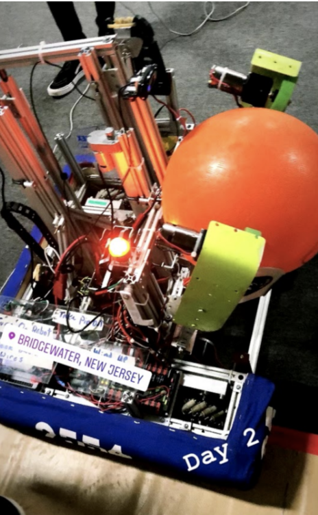
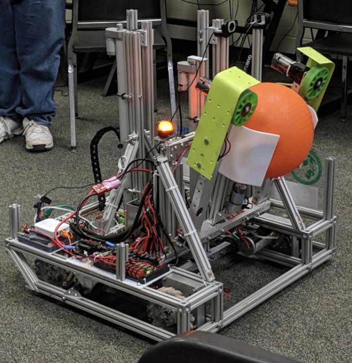
Robot Documentation
Drive Train
- Mecanum drive train from kit bot adjusted to remove top layer of extruded aluminum to mount the shooter and actuators
Intake/Output/Shooter
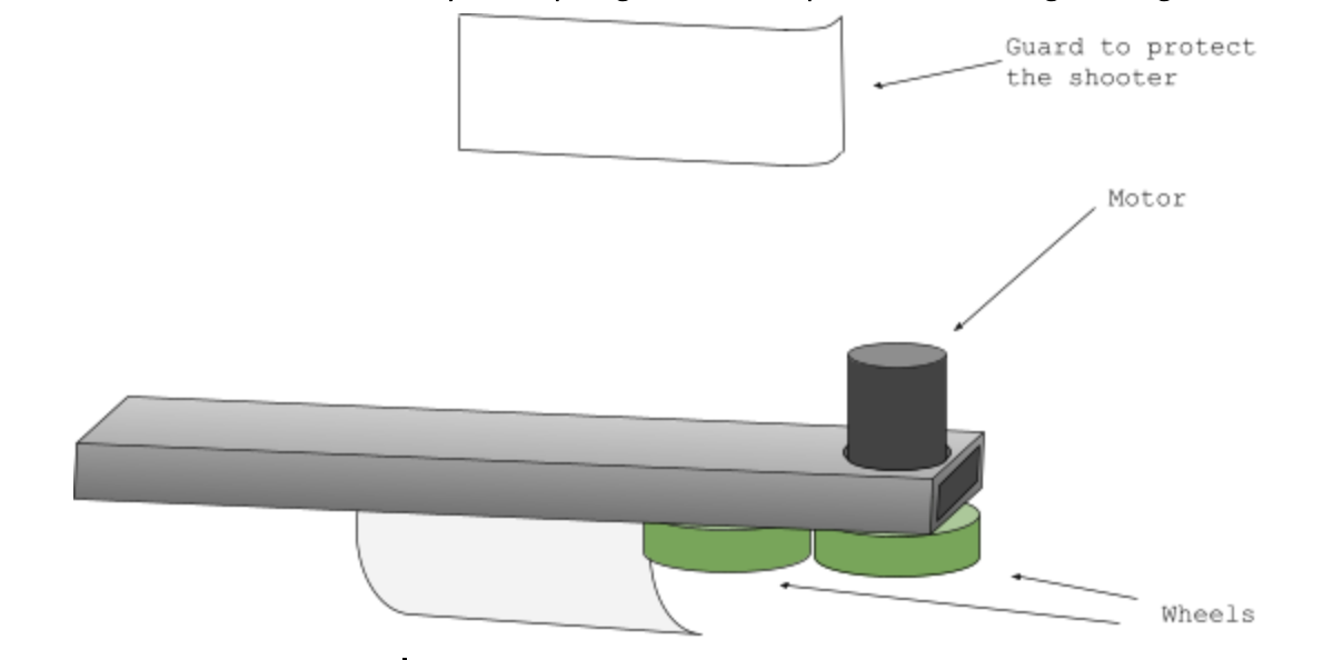
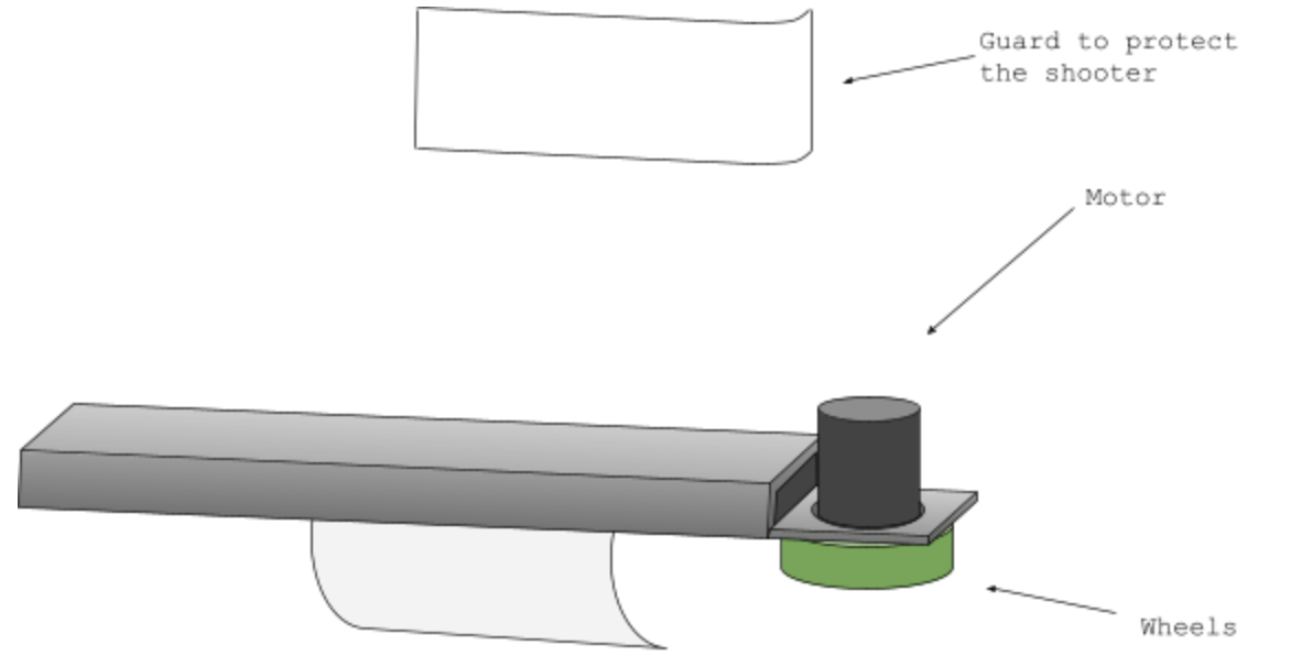
Original Shooter
- 2 Wheels on both sides, lined up side by side and linked by a chain, on the bottom of the metal bar
- Motor was on top of the metal bar, with a hole cut into the metal for the motor to fit.
- We had two arms like this on the shooter, one on each side. The wheels were linked by a chain, meaning both the wheel directly connected to the motor and the one not connected would rotate at the same rate.
- Pieces of acrylic were used to create a curved holder for the balls. One was attached to the inner side of each arm.
- The guard shown at the top was located on the outer side of each arm and made of plexiglass.
- Both the acrylic and plexiglass were shaped and bent using a heat gun.
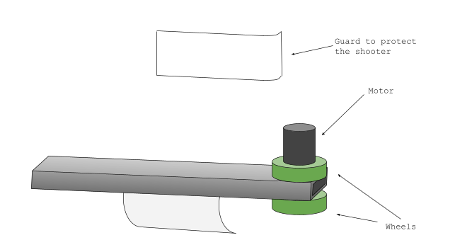
Changed Shooter
The 2 wheels were vertically aligned rather than bound by a chain.
One wheel on top of the bar, one on the bottom, linked by an axle.
Motor remained on top.
Final Shooter
- One wheel on each side, rather than two
- Guards changed to bent pieces of metal
- Material removed from the end to create a thin sheet
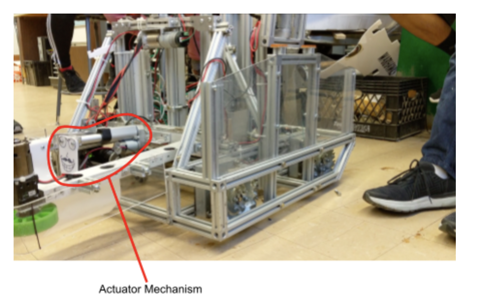
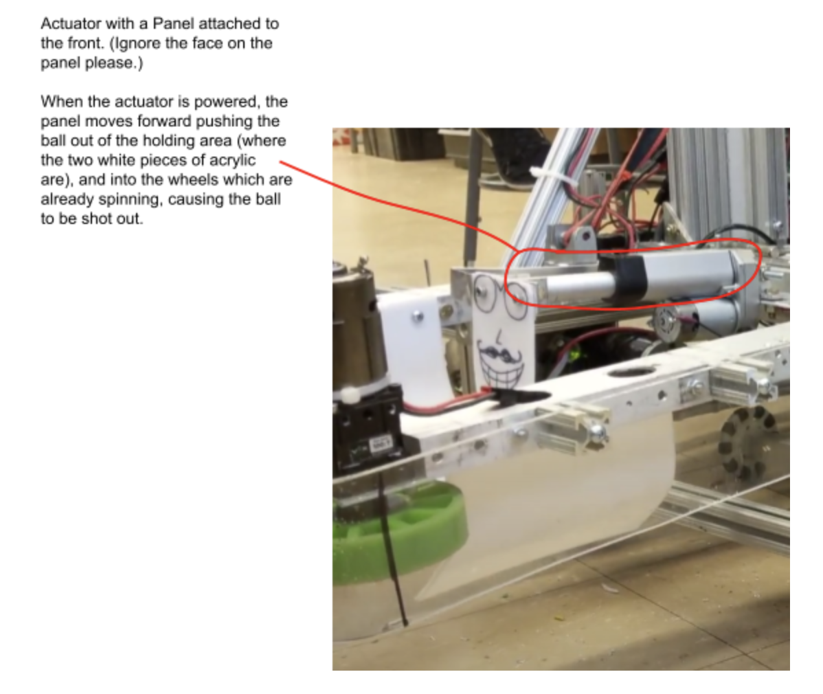
Actuator Mechanism on Shooter
- After the shooter mechanism intakes a ball, the ball rests on the plate of the actuator without touching the wheels of the shooter
- When shooting the ball, the actuator is extended to push the ball back into the wheels
Usage
- At the beginning of each round, the hinge is lowered down as much as possible
- The robot moves to intake a ball with the shooter
- When the robot moves to the area to score, it raises the hinge to the proper angle
- The actuator is extended to launch the ball
- Usage of Shooter (Includes usage of hinge)
Claw
- Design utilized an actuator with a wedge attached to the end.
- Medical Tubing was used to create tension.
- Usage
- When the actuator extended, the wedge would push between the two parts of the claw, bringing the ends apart. This would be done after the claw was inserted into the center of the hatch. Grooves in the outside of the arms would grab onto the inner rim of the hatch and keep it secure. After bringing it over to one of the rockets, retracting the actuator would allow the claws to move inwards, letting go of the hatch and placing it on the rocket.
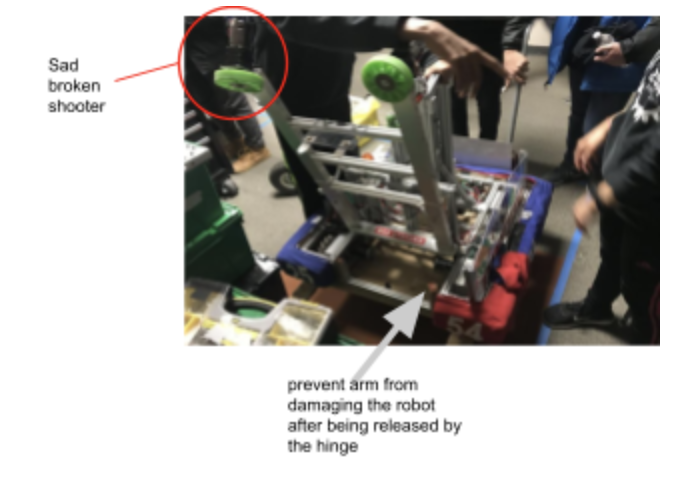
- Attached to a freely swinging hinge. There was a lock on the hinge which would slide into a hole in one of the pieces of extruded aluminum. Lock would be removed at the beginning of each match, so that when the robot had enough sudden movement, the hinge would swing down and allow us to use the claw.
- Design: Ask Mr. Kearney for 3-d claw design
Shooter Hinge
- Design
- Motor positioned on an elevated beam. The motor had an axle coming out, which had a strap starting from the shooter attached to it. Turning the motor in one direction would wind up the strap and pull up the shooter, while turning it in the other direction would gradually lower the shooter.
- Had to make sure the strap had a lot of tension, so that the shooter couldn’t randomly bounce around.
- Purpose 3. Release intake/shooter mechanism after round starts to follow perimeter restrictions.
- Issues 4. Awkward design made from washers and acrylic (which formed the hook which attached to the intake/shooter mechanism) 5. Caused damage to the aluminum of the shooter
- Usage (See: “Intake/Output/Shooter” - Usage)
Actuators
- Purpose
- Bottom of Actuators was an aluminum rod with free rolling Wheels attached to the actuators.
- Back Actuator had Seed Motor that was used to move back and forth when robot was off ground
- Other Attempts:
- Pneumatics was attempted in small team and while mechanism was successful with regular robot, the eventual robot was too heavy to implement feasibly and thus scrapped
- Elevator idea was brought up but eventually
- Actuators in Climbing + In-Game Implementation Testing Actuators
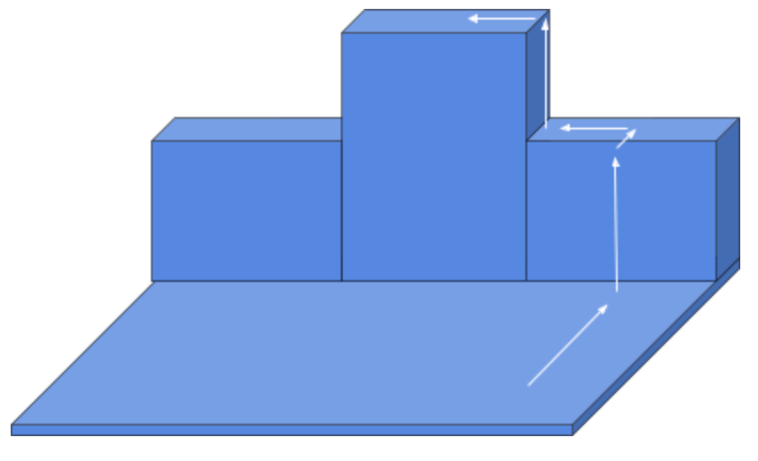
- Approach level 1 platform
- Extend both actuators
- Power the wheels attached to the back actuator and go forward until the front of the robot is on top of the level 1 platform and the front actuator/set of wheels is close to said platform
- Retract front actuator
- Power the back wheels again and also the front set of main wheels so that the majority of the robot is on top of the level 1 platform
- Retract back actuator and use main wheels to completely bring the robot on to the platform
- For level 2 climb, repeat the same process, but after doing a ninety degree turn when on the level 1 climb
- Actuators in Shooter
- There was an actuator placed at the back of the shooter
- Goal was not for the actuator to cause the ball’s motion, but rather to push the ball from the holding area into the wheels, where it would then be shot out
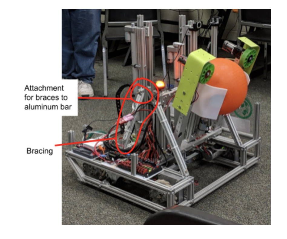
Bracing + Misc.
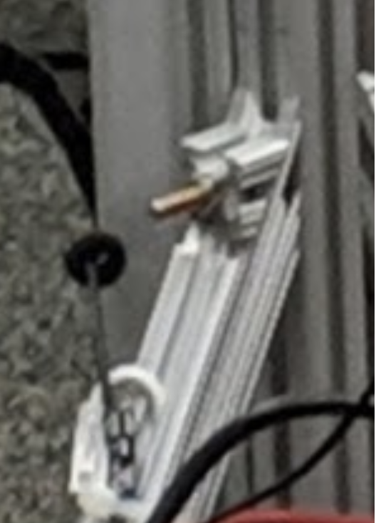
- Angled Braces
- Purpose
- Prevent the extruded aluminum bars holding the actuators that raise the robot from swaying
- Process of Creating
- Cut a piece of extruded aluminum at an angle with the miter saw on both ends to create the angle seen in the image below
- Process: Cut top ends of the aluminum bar (which forms the brace) off to allow for space to attach the attachment to the aluminum bar (see images below)
- Drill a hole perpendicular to the aluminum bar being supported into the brace bar and attach with a bolt. To best drill this hole, do so from the inner side of the extruded, where the angled cut took place. The hole in the extruded will already be there for centering/guiding purposes, and it eliminates the concern of having to line it up.
- Purpose
- Bracing between “Pillars”
- Purpose
- Prevent “pillars” from swaying as the robot moves
- Plexi-Glass/Acrylic
- Plexi-glass used to cover E-Board to protect from metal shavings
- Plexi-glass panel on the side to show the names of sponsors
- Acrylic originally used in shooter-guards
- Acrylic used to form a holding zone for the ball between the actuator and wheels